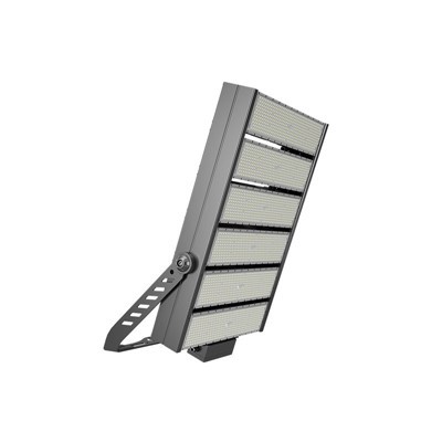

What is an LED chip? So what are its characteristics? LED chip manufacturing is mainly to produce effective and reliable low-ohm contact electrodes, and can meet the relatively small voltage drop between the contactable materials and provide a pressure pad for bonding wires. Give out as much light as possible. The film transition process generally uses a vacuum evaporation method. Under a high vacuum of 4Pa, the material is melted by resistance heating or electron beam bombardment heating, and BZX79C18 becomes a metal vapor deposited on the surface of the semiconductor material under low pressure.

P-type contact metals generally used include alloys such as AuBe and AuZn, and AuGeNi alloy is often used as the contact metal on the N surface. The alloy layer formed after plating also needs to expose as much of the light-emitting area as possible through a photolithography process, so that the remaining alloy layer can meet the requirements of effective and reliable low-ohm contact electrodes and wire bonding pads. After the photolithography process is completed, an alloying process is required. The alloying is usually carried out under the protection of H2 or N2. The alloying time and temperature are usually determined by factors such as the characteristics of the semiconductor material and the form of the alloy furnace. Of course, if the chip electrode process such as blue and green is more complicated, it is necessary to increase the passivation film growth and plasma etching process.
In the LED chip manufacturing process, which process has a more important impact on its photoelectric performance?
Generally speaking, after the LED epitaxial production is completed, its main electrical properties have been finalized, and the chip manufacturing does not change the nature of its core production, but improper conditions in the coating and alloying process will cause some electrical parameters to be poor. For example, low or high alloying temperature will cause poor ohmic contact. Poor ohmic contact is the main reason for the high forward voltage drop VF in chip manufacturing. After cutting, if some etching processes are performed on the edge of the chip, it will be better to improve the reverse leakage of the chip. This is because after cutting with a diamond grinding wheel blade, more debris and powder will remain on the edge of the chip. If these are stuck to the PN junction of the LED chip, it will cause leakage and even breakdown. In addition, if the photoresist on the surface of the chip is not peeled cleanly, it will cause difficult and false soldering on the front side. If it is the back side, the voltage drop will also be high. In the chip production process, the light intensity can be increased by roughening the surface and dividing into an inverted trapezoid structure.

Why are LED chips divided into different sizes? What are the effects of size on the photoelectric performance of LEDs?
LED chip size can be divided into low-power chips, medium-power chips and high-power chips according to the power. According to customer requirements, it can be divided into categories such as single tube level, digital level, dot matrix level and decorative lighting. As for the specific size of the chip, it is determined according to the actual production level of different chip manufacturers, and there is no specific requirement. As long as the process passes, the chip size can increase the unit output and reduce the cost, and the photoelectric performance will not change fundamentally. The current used by the chip is actually related to the current density flowing through the chip. A small chip uses a small current, and a large chip uses a large current. Their unit current density is basically the same. Considering that heat dissipation is the main problem under high current, its luminous efficiency is lower than that of low current. On the other hand, as the area increases, the body resistance of the chip will decrease, so the forward conduction voltage will decrease.
LED high-power chip generally refers to what area of chip? Why?
The high-power LED chips used for white light are generally around 40mil in the market. The so-called high-power chips generally refer to electric power above 1W. Since the quantum efficiency is generally less than 20%, most of the electrical energy will be converted into heat, so the heat dissipation of the high-power chip is very important, and the chip is required to have a larger area.
What are the different requirements of the chip technology and processing equipment for manufacturing GaN epitaxial materials compared with GaP, GaAs, and InGaAlP? Why?
The substrates of ordinary LED red and yellow chips and high-brightness quaternary red and yellow chips are made of compound semiconductor materials such as GaP and GaAs, and they can generally be made into N-type substrates. The wet process is used for photolithography, and then a diamond wheel blade is used to cut into chips. The blue-green chip of GaN material is a sapphire substrate. Since the sapphire substrate is insulated, it cannot be used as a pole of the LED. The P/N two electrodes must be made on the epitaxial surface through a dry etching process. Some passivation processes are also required. Because sapphire is very hard, it is difficult to divide into chips with a diamond wheel blade. Its process is generally more and more complicated than that of GaP and GaAs LEDs.
What are the structure of the "transparent electrode" chip and its characteristics?
The so-called transparent electrode must first be able to conduct electricity, and secondly, be able to transmit light. This material is now more widely used in the liquid crystal production process, its name is indium tin oxide, the English abbreviation ITO, but it cannot be used as a soldering pad. When making, first make ohmic electrodes on the surface of the chip, and then cover a layer of ITO on the surface and then plate a layer of bonding pads on the surface of the ITO. In this way, the current coming down from the lead is uniformly distributed to each ohmic contact electrode through the ITO layer. At the same time, since the refractive index of ITO is between the refractive index of the air and the epitaxial material, the light output angle can be increased and the luminous flux can also be increased.

What is the mainstream of the development of chip technology for semiconductor lighting?
With the development of semiconductor LED technology, its applications in the field of lighting are also increasing, especially the emergence of white LEDs, which has become a hot spot for semiconductor lighting. However, the key chip and packaging technology needs to be improved, and the chip should be developed towards high power, high luminous efficiency and lower thermal resistance. Increasing power means increasing the current used by the chip. The more direct way is to increase the size of the chip. Nowadays, the high-power chips generally appearing are around 1mm×1mm, and the current is 350mA. Due to the increase of the current, the heat dissipation problem becomes The outstanding problem is now basically solved by the chip flip method. With the development of LED technology, its application in the field of lighting will face an unprecedented opportunity and challenge.
What is a "flip chip? What is its structure? What are its advantages?
Blue LEDs usually use Al2O3 substrates. Al2O3 substrates have high hardness, low thermal conductivity and low electrical conductivity. If the front-mounted structure is adopted, on the one hand, it will bring about anti-static problems, on the other hand, heat dissipation will also become a problem under high current conditions. The main problem. At the same time, since the front electrode faces upward, a part of the light will be blocked, and the luminous efficiency will be reduced. High-power blue LEDs can obtain more effective light emission through chip flip-chip technology than traditional packaging technology.
The current mainstream flip-chip structure method is: first prepare a large-size blue LED chip with suitable eutectic welding electrodes, and at the same time prepare a silicon substrate slightly larger than the blue LED chip, and fabricate gold for eutectic welding. Conductive layer and lead wire layer (ultrasonic gold wire ball solder joints). Then, the high-power blue LED chip and the silicon substrate are welded together using eutectic welding equipment.
The feature of this structure is that the epitaxial layer is in direct contact with the silicon substrate, and the thermal resistance of the silicon substrate is much lower than that of the sapphire substrate, so the heat dissipation problem is solved well. Since the sapphire substrate faces up after flipping, it becomes the light-emitting surface, and the sapphire is transparent, so the light-emitting problem is also solved. The above is the relevant knowledge of LED technology. I believe that with the development of science and technology, the future LED lights will become more and more efficient, and the service life will be greatly improved, which will bring us greater convenience.